Engine Indicating & Crew Alerting System (EICAS) (14.13)
The basic system comprises two display units, a control panel and two computers supplied with analog and digital signals from the engine and system sensors. The computers are designated “Left” and “Right” and only one is in control of the system at any one time, the other is held in standby. In the event of a failure, it may be switched in either manually or automatically.
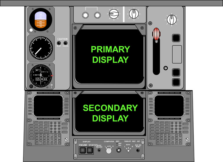
Operating in conjunction with the system are discrete caution and warning lights, standby engine indicators and a remotely-located panel for selecting maintenance data display. The system provides the flight crew with information on primary engine parameters (Full-time), with secondary engine parameters and advisory/caution/warning alert messages displayed as required. Figure 26 shows layout of the EICAS Displays.
EICAS displays
Figure 26
14.13.1 Display Units
These units provide a wide variety of information relevant to engine operation and operation of other automated system. The operation of these displays is as for those in the EFIS as previously described.
The upper unit displays primary engine parameters, i.e. N1 speed, EGT, and warning and caution messages. The lower unit displays secondary parameters, i.e. N2 speed, fuel flow, oil quantity, pressure and temperature. In addition, the status of non-engine systems e.g. flight control surface position, hydraulic system, APU, etc., can be displayed.
On the upper unit, a row of Vs will appear when secondary information is being displayed on the lower unit. Seven colours are produced by the CRTs for displaying information. These have the following functions

Figure 27 and 28 show display formats for primary and secondary displays respectively.
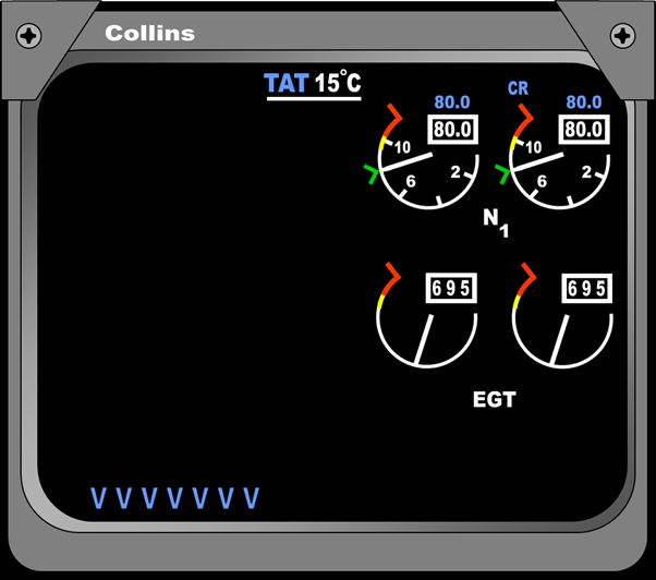
EICAS Primary display
Figure 27
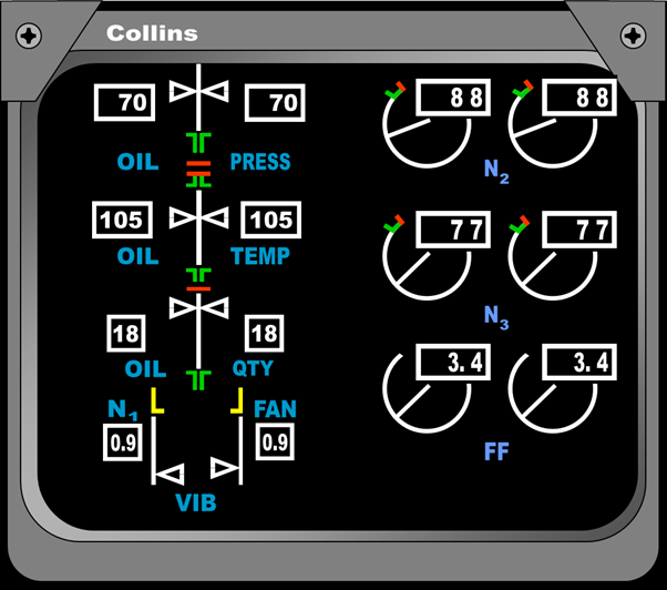
EICAS secondary display
Figure 28
14.13.2 Display Modes
EICAS is designed to categorize displays and alerts according to the function and usage. For this purpose there are three modes of displaying information:
1. Operational (selected by the flight crew).
2. Status (selected by the flight crew).
3. Maintenance (ground use only and selected via the maintenance panel).
14.13.3 Operational Mode
This mode displays the engine operating information and any alerts requiring action by the crew in flight. Normally only the upper display unit presents information: the lower one remains blank and can be selected to display secondary information as and when required.
14.13.4 Status Mode
When selected this mode displays data to determine the dispatch readiness of an aircraft, and is closely associated with details contained in the aircraft’s Minimum Equipment List. The display shows the positions of the flight control surfaces in the form of pointers registered against vertical scales, selected sub-system parameters, and equipment status messages on the lower display unit. Selection is normally done on the ground, either as part of the pre-flight checks of dispatch items, or prior to shutdown of electrical power to aid the flight crew in making entries in the aircraft’s Technical log. Figure 29 shows an example of a status page.
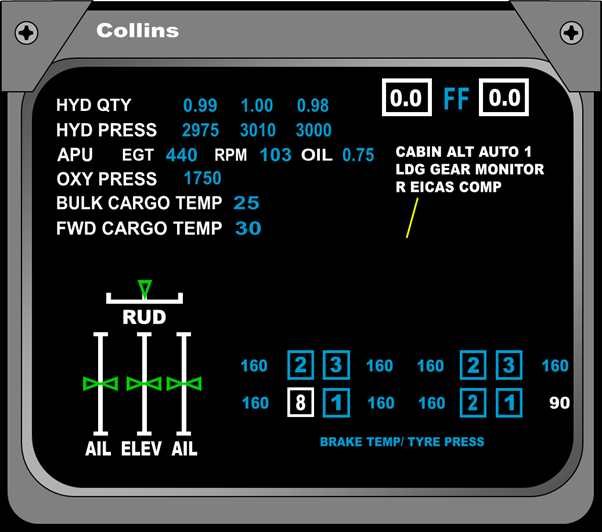
EICAS Status page display
Figure 29
14.13.5 Maintenance Mode
This mode provides maintenance engineers with information in five different display formats to aid them in fault finding and verification testing of major sub-systems.
14.13.6 Display Select Panel
To control the operation of the EICAS, a control panel is situated on the centre pedestal. Figure 30 shows a typical EICAS control panel.

Figure 30
14.13.7 Display Select Panel Operation
Engine Display Switch: This is a push type switch for removing or presenting the display of secondary information on the lower display.
Status Display Switch: This is a push type switch for removing or presenting the status page on the lower display.
Event Record Switch: Normally, there is an auto event function and this will automatically record any malfunctions as they occur. The push switch enables manual event marking so that the crew can record a suspect malfunction for storage in a non-volatile memory. This data can be retrieved from the memory and displayed by ground engineers by operating the ground maintenance panel. The manual switch can also be used for activating the recording of fault data, either in the air or on the ground, on the Environmental Control system, Electrical Power system, Hydraulic system and APU.
Computer Select Switch: In the “AUTO” position it selects the left, or primary computer and automatically switches to the other in the event of a failure. The other positions are for manually selecting either the right or left computers.
Display Brightness: Controlled by the inner knob for the display intensity, the outer for display brightness.
Thrust Reference Set Switch: Pulling and rotating the inner knob positions the reference cursor on the thrust indicator display (either EPR or N1) for the engines, which are selected by the outer knob.
Max Indicator Reset: If any of the measured parameters e.g. Oil Pressure, EGT etc. exceed normal operating limits, it will be automatically alerted on the display units. The purpose of the reset button is to clear the alerts from the display when the excess limits no longer exist.
14.13.8 Alert Messages
The system will continually monitor a large number of inputs (400+) from engine and airframe systems. If a malfunction is detected, then the appropriate alert message is annunciated on the upper display. Up to 11 messages can be displayed and are at the following levels:
LEVEL A - Warning: Requiring immediate corrective action and are displayed in “RED”. Master warning lights are also activated and aural warnings from the Central Warning System are given.
LEVEL B - Caution: Requiring immediate crew awareness and possible action. They are displayed in “AMBER”. An aural tone is also repeated twice.
LEVEL C - Advisory: Requiring crew awareness, displayed in “AMBER”. There are no caution lights or aural tones associated with this level.
Figure 31 shows a display with the three different types of alert messages displayed on the Upper EICAS.

EICAS alert messages
Figure 31
14.13.9 Maintenance Control Panel
The panel is used by maintenance engineers for displaying maintenance data stored within the system’s computer memories. Figure 32 shows a typical maintenance control panel with Figure 33 showing the ELEC/HYD Maint page.

Maintenance Control Panel
Figure 32
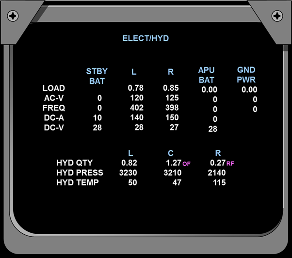
EICAS ELEC/HYD Maint page
Figure 33