BIT Functions on EFIS (14.15)
A limited BIT function is available on EFIS Systems. The EFIS PFD and ND are used to verify the test outputs of the various avionic systems supplying data to the EFIS. When, for example, the LRRA system is put into test mode, the LRRA output is set to 40ft and this is verified by the engineer by observing the LRRA output changing to this value on the PFD. In another example, the ADF test bearing is 135 degrees and, when put into test mode, the engineer verifies the ADF bearing pointer has driven to this bearing on the ND.
Additionally, the EFIS itself can be put into VERIFY mode via a guarded switch on the Maintenance and Test Panel (MTP). On selection, the EFIS displays show identical displays on both the PFD and ND. During this initial period, the EFIS system performs a self-test on its software and hardware functions and the results of the test are displayed to the engineer after a few seconds have elapsed, see Figure 44. The page indicates the results of a SUM CHECK and RAM TEST as well as showing the status of the various ARINC and DISCRETE inputs to the EFIS. Additionally, a RASTER TEST PATCH allows the engineer to confirm that the colour outputs are satisfactory.
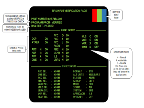
EFIS Verification page (both PFD and ND screens)
Figure 44
An additional ARINC DIAGNOSTICS page is available showing the LABEL, SDI, SSM and DATA for each input to a selectable system, see Figure 45.
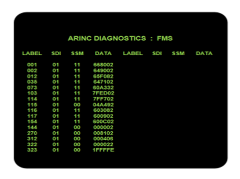
EFIS ARINC DIAGNOSTICS page (both PFD and ND screens)
Figure 45