Electronic Centralised Aircraft Monitoring (ECAM) (14.4)
ECAM differs from EICAS in that the data displayed relate essentially to the primary systems of the aircraft and are displayed in checklist and pictorial or synoptic format.
14.14.1 Display Units
These can be mounted either side-by-side or top/bottom. The left-hand/top unit is dedicated to information on the status of the system; warnings and corrective action in a sequenced checklist format, while the right-hand/bottom unit is dedicated to associated information in pictorial or synoptic format. Figure 34 shows the layout of ECAM displays.

ECAM displays
Figure 34
14.14.2 ECAM Display Modes
There are four display modes, three of which are automatically selected and referred to as:
1. Phase-Related Mode.
2. Advisory Mode.
3. Failure-Related Modes.
The fourth mode is manual and permits the selection of diagrams related to any one of 12 of the aircraft’s systems for routine checking, and also the selection of status messages, provided no warnings have been triggered for display.
14.14.3 Flight Phase Related Mode
In normal operation, the automatic flight phase-related mode is used and the displays will be appropriate to the current phase of aircraft operation, i.e. Pre-flight, Take-off, Climb, Cruise, Descent, Approach, and post landing. Figure 35 shows display modes. The upper display shows the display for pre-take off, the lower is that displayed for the cruise.
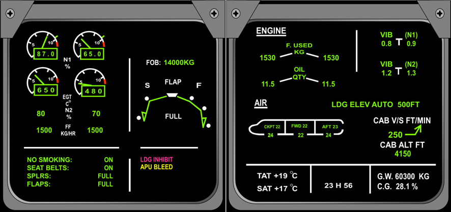
ECAM Display modes
Figure 35
14.14.4 Advisory Mode
This mode provides the flight crew with a summary of the aircraft’s condition following a failure and the possible downgrading of systems. Figure 36 shows an advisory message.

ECAM Advisory message
Figure 36
14.14.5 ECAM Failure Mode
The failure-related mode takes precedence over the other modes. Failures are classified in 3 levels
Level 3: Warnings
This corresponds to an emergency configuration. This requires the flight crew to carry out corrective action immediately. This warning has an associated aural warning (fire bell type) and a visual warning (Master Warning), on the glare shield panel.
Level 2: Cautions
This corresponds to an abnormal configuration of the aircraft, where the flight crew must be made aware of the caution immediately but does not require immediate corrective action. The flight crew decide on whether action should be taken. These cautions are associated to an aural caution (single chime) and a steady (Master Caution), on the glare shield panel.
Level 1: Cautions
This gives the flight crew information on aircraft configuration that requires monitoring, mainly failures leading to a loss of redundancy or degradation of a system, e.g. Loss of 1 FUEL TANK PUMP LH or RH but not both.
The advisory mode will not trigger any aural warning or ‘attention getters’ but a message appears on the primary ECAM display.
14.15.6 Control Panel
The control panel allows selection of the display for system and status images. The layout of the control panel is shown in Figure 37.
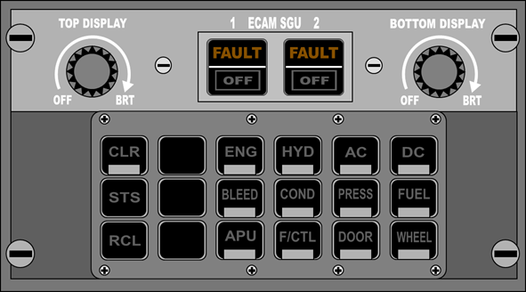
Figure 37
SGU Selector Switches:
Controls the respective symbol generator units. Lights are off in normal operation of the system. ‘FAULT’ is illuminated amber if an SGU internal test
circuit detects a failure. Releasing the switch isolates the corresponding SGU and causes the ‘FAULT’ caption to extinguish and the ‘OFF’ caption to
illuminate white.
System Synoptic Display Switches:
Permit individual selection of synoptic diagrams corresponding to each of the 12 systems and illuminate white when pressed. A display is automatically
cancelled whenever a warning or advisory occurs.
CLR Switch:
Light illuminates white whenever a warning or status message is displayed on the left-hand display unit. Press to clear messages.
STS Switch:
Permits manual selection of an aircraft’s status message if no warning is displayed. Illuminates white when pressed also illuminates the CLR switch.
Status messages are suppressed if a warning occurs or if the CLR switch is pressed.
RCL Switch:
Enables previously cleared warning messages to be recalled, provided the failure conditions which initiated the warnings still exists. Pressing this
switch also illuminates the CLR switch. If a failure no longer exists, the message ‘NO WARNING PRESENT’ is displayed on the left-hand display unit.
Figure 38 – 42 shows the 12-system pages and status page available.
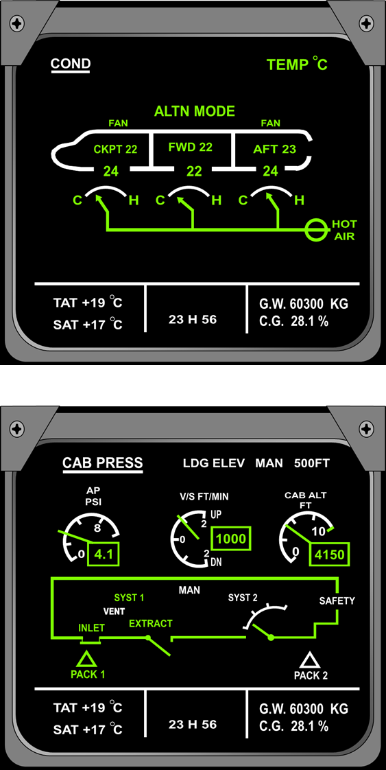
Figure 38
Note: These pages are displayed:
Automatically due to an advisory or failure related to the system.
Whenever called manually.
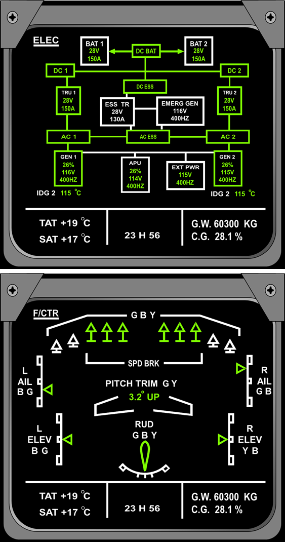
Figure 39
Note: These pages are displayed:
Automatically due to an advisory or failure related to the system.
Whenever called manually.
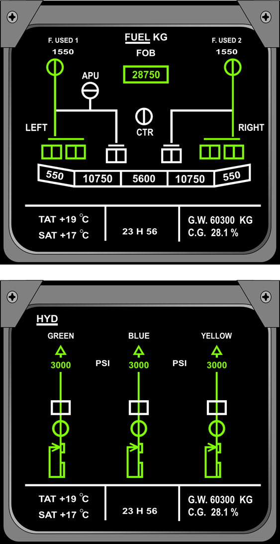
Figure 40
Note: These pages are displayed:
Automatically due to an advisory or failure related to the system.
Whenever called manually.
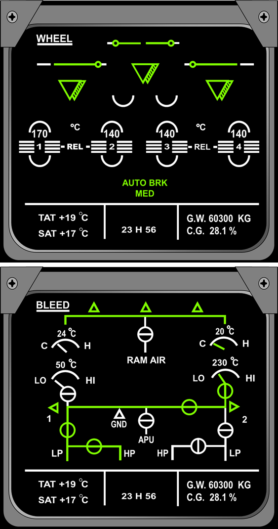
Figure 41
Note: These pages are displayed:
Automatically due to an advisory or failure related to the system.
Whenever called manually.
The Gear/Wheel page is displayed at the related flight phase.
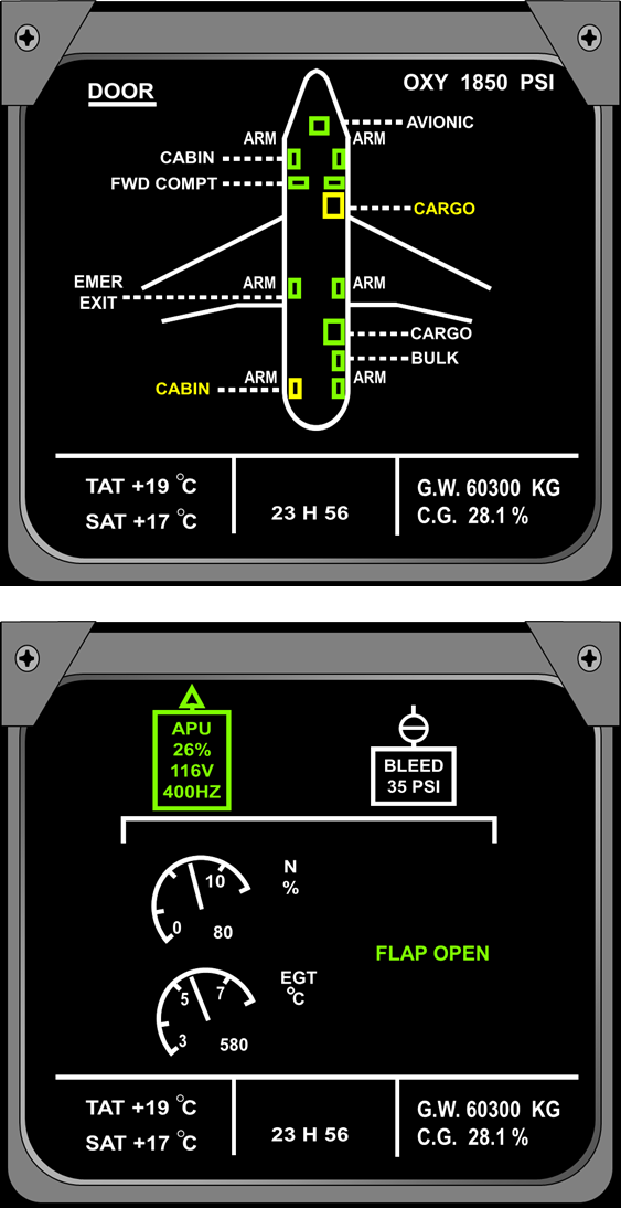
Figure 42
Note: These pages are displayed:
Automatically due to an advisory or failure related to the system.
Whenever called manually.
Related flight phase.
14.14.7 Status Display
The STATUS mode is selected:
Automatically after a warning message, as soon as all corrective actions have been performed.
1. By pressing the CLR key (if there is no STATUS, MEMO is directly displayed)
2. Manually by pressing the STS key.
3. The status page of the aircraft gives:
On the left part of the display an operational summary of the aircraft conditioning, listing all the failures having consequences upon operational aspects, such as:
1. Emergency procedures (LAND ASAP).
2. Landing capability and procedures.
3. Limitations (Speed/Altitude).
4. Postponable procedures not displayed on first page.
5. Lost system or function.
6. Information.
On the right part of the display the so-called secondary failures or losses of system/equipment resulting from the origin or primary failure.
There is a Fault Warning Computer (FWC) which generates the status messages.
Figure 43 shows a typical status page.
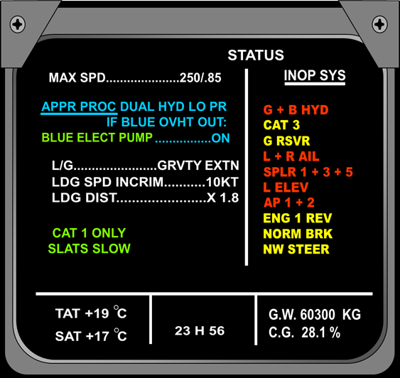
ECAM Status page
Figure 43