Head Up Display (14.16)
14.16.1 Head Up Display System
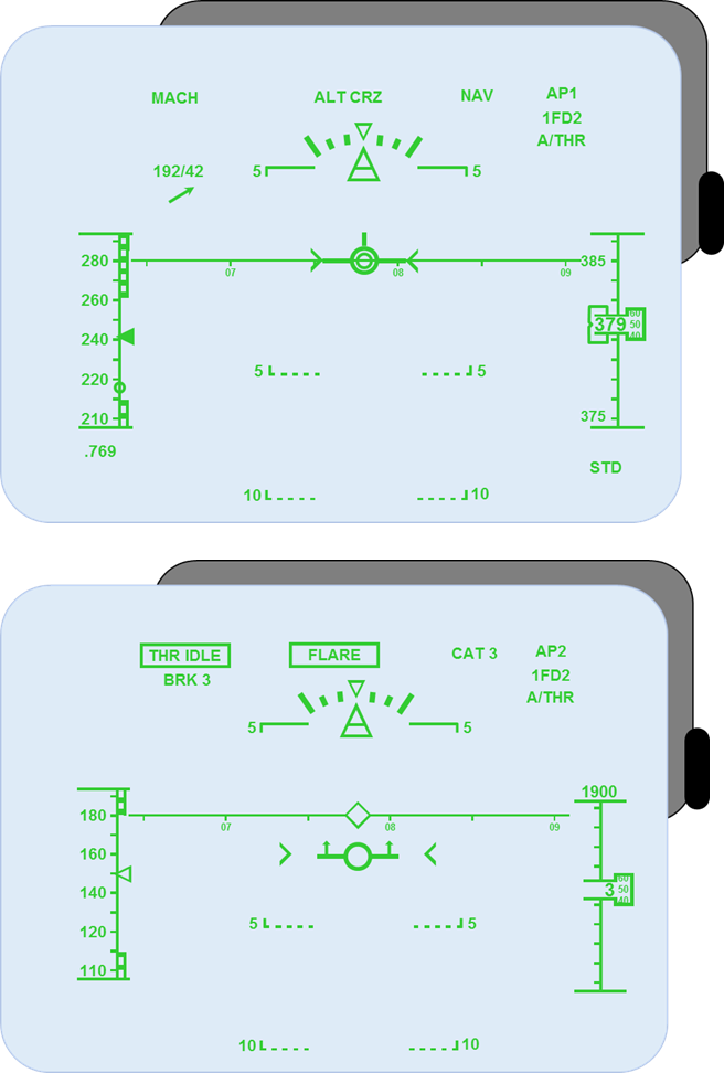
Head-up displays (HUDs) provide pilots with an array of flight-related information, when and where they need it most. The HUD combiner glass, which folds down and locks into position in front of the pilot’s eyes, displays PFD related flight data and symbology directly in the forward field of vision. On a non-precision approach at night or in poor weather, this information is of huge value, particularly when viewed in the context of past aircraft accident investigations. Figure 46 shows an A350 Head-Up Display with the aircraft at altitude and during landing phase.
Head-Up Display (HUD)
Figure 46
Early HUDs developed for civil aviation typically showed the same data that was available on a head-down primary flight display (PFD), namely airspeed, altitude, localiser, glideslope and so on. Today’s HUDs offer a far broader menu of symbology, including a flight-path marker, path and airspeed trend vectors, angle-of-attack readout, runway depictions, landing-flare cues, runway-remaining information, tail-strike warning, unusual-attitude-recovery symbology, TCAS resolution advisories and other vital data. Add to this list the recent certification of HUD-based infrared enhanced-vision systems (EVS) and the ongoing research of database-derived synthetic-vision systems (SVS), and the potential value of HUDs as a tool for improved situational awareness is readily evident.
14.16.2 Functional Overview
The HUD system is used for a wide variety of flight guidance functions available to the flight deck crew in all phases of flight, including take-off and landing. HUD also provides a visual aid for airport surface operations.
The HUD system components generally comprise the following units:
- HUD Display Computer (HUDC).
- HUD Projection Unit (HPU).
- HUD Combiner Unit (HCU).
- Personalised Memory Module (PMM).
Figure 47 shows a typical HUD layout.
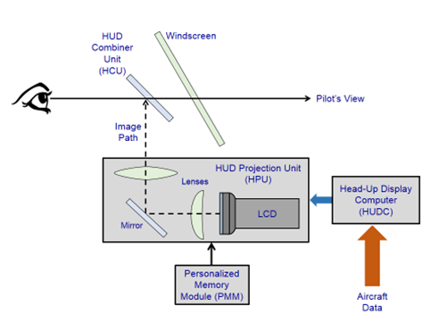
HUD Schematic
Figure 47
14.16.3 Head-Up Display Computer (HUDC)
The HUDC receives data on the aircraft’s flight and navigational aids from the Aircraft Information System via the ARINC 629 data bus. It processes this information and generates the display graphics and outputs video pulses to the Head-Up Projection Unit (HPU) for the required display symbology. It also incorporates Built-In Test Equipment (BITE) for system self-monitoring and fault data storage.
14.16.4 Head-Up Projection Unit (HPU)
The HPU receives video pulses from the HUDC and uses these signals to generate the required display on to a LCD screen. The use of LCD technology offers additional graphic capabilities and a good quality of legibility of the symbology. The image from the LCD is projected via a mirror and various lenses on to the Combiner Unit.
14.16.5 Head-Up Combiner Unit (HCU)
The HCU consists of an optical unit (Glass Plate) which is mounted behind the aircraft’s windshield. The HCU reflects the projected image from the HPU towards the pilot. Whilst the superimposed image, which is focused to infinity, provides the flight crew with flight information, they can continue to observe external ground reference points during each phase of flight. The HCU is hinged so that when not required it can be stored away out of the pilot’s field of view. Figure 47 shows a HCU
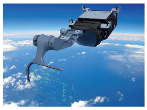
Head up Combiner Unit (HCU)
Figure 48
14.16.6 Personalized Memory Module (PMM)
The PMM is used for storing the electronic bore sighting parameters for that particular aircraft. This involves an electronic process which aligns the optical reference of the HUD flight-deck equipment with that of the aircraft and this avoids the need to repeat the process should a HUD LRU be replaced. Figure 49 shows a schematic of an Airbus Industries Head-Up Display System.
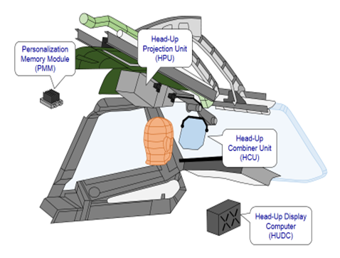
HUD System (Airbus Industries)
Figure 49
14.16.7 HUD Symbology
The primary aim of the HUD symbology is to provide essential flight data and the information required for the safe and effective control of the aircraft. It is necessary for the symbology to accurately represent the outside (conformal) view, while not obstructing the outside view. The following items are unique to HUD symbology:
Conformal Elements – Some HUD symbols are designed to overlay the real world as seen by the pilot through the HUD Combiner Unit (HCU).
Viewing Position – The HUD is designed to be viewed from the flight-deck eye reference point and a head movement around this point called the “Eye Motion Box”.
Viewing into the Sun – The HUD is designed to be able to project symbology that can be seen against a very bright background (3400 Cd/m2). The pilots can also use a dedicated Sun-Visor to reduce the intensity of the sun and can set the brightness of the symbology so that it can be seen (or use an automatic brightness feature).
The core symbology of the HUD is the Attitude/Energy Box, which is composed of;
- Aircraft Attitude (Pitch, Roll, side-slip and heading).
- Flight Path Vector (FPV).
- The Total Flight Path Angle (TFPA).
- Airspeed Scale.
14.16.8 Flight Path Vector (FPV)
The FPV indicates the actual aircraft’s trajectory through the aircraft’s Flight Path Angle (FPA) as the longitudinal component of the aircraft’s drift angle as the lateral component.
14.16.9 Total Flight Path Angle (TFPA)
The TFPA is represented on the display by two chevrons which indicate the actual total energy of the aircraft (both Potential and Kinetic). It provides indications of the aircraft’s acceleration and deceleration. Along with the FPV, it assists the pilots is controlling the aircraft’s airspeed and flight path stability during an approach. Figure 50 shows FPA, TFPA & FPV indications.

FPA, TFPA & FPV Indications
Figure 50
The HUD system improves the flight crew’s situational awareness and therefore contributes to the safety of the aircraft is providing:
- Situational awareness for the manual visual approach and landing.
- Enhanced stability of a manually flown approach (Instrument and visual approach).
- Enhanced pilot situational awareness when close to the ground by showing confrontal trajectory related symbols superimposed to the symbols
superimposed to the external scene.
- Situational information for the monitoring of automatic approaches with Autoland Cat II & Cat III approaches.
Figure 51 shows a HUD display for an aircraft approaching the touchdown point.
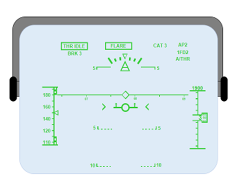
HUD Approach Display
Figure 51